
CHLORINATORS
Hypochlorinators
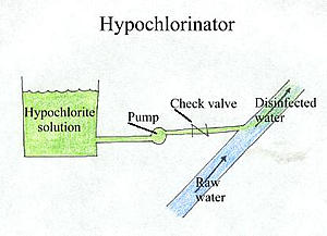
The simplest method of continuous chlorination of water supply systems for a water flow of less than 200 Lpm is by the use of a hypochlorinator. Hypochlorinators are motor driven pumps which are used to add hypochlorite solutions to water. The pump pulls the hypochlorite solution out of a holding chamber and pumps it into the water to be treated. Where the pipe from the pump joins the pipe carrying the raw water, the venturi effect creates a small vacuum and pulls the chlorine solution into the water. The below figure shows the hypochlorinator.

Hypochlorinator
It is often necessary to increase or decrease the amount of chlorine added to the water as conditions change. In hypo chlorinators the amount of chlorine fed into the water is adjusted either by varying the stroke length or machine speed. Further the amount of chlorine added can be adjusted by changing the strength of the hypochlorite solution. Hypochlorinators are usually used to perform continuous chlorination in smaller systems.
Chlorinators
Chlorinators are devices which introduce chlorine solution to water. Chlorinators are more economical when the supply source is greater than 200 Lpm and may sometimes be used in smaller systems as well. NaCl is hydrolyzed to chlorine (Cl) and NaOH. By pressurizing the Cl gas at 4 to 7 ksc pressure, Cl gas is converted into liquid and the liquified chlorine gas is filled and stored in the cylinders of 48.4-kg and 68-kg capacity or in 907-kg (one-ton) container. The Cl cylinders are most likely applied to small water supply systems. The 907-kg containers are generally used for moderate size water treatment plant. In each case, the liquid expands back into a gas as it leaves the cylinder. Whenever a substance changes state from a liquid form to a gaseous form, heat is required. The heat which is absorbed by the chlorine as it changes state in the cylinder comes from the surrounding air.
If chlorine is drawn off from a cylinder too quickly, the temperature of the air surrounding the tank will drop and will cause frosting and lower gas flow. To prevent frosting, the draw off rate should be not greater than150 kg of gas per day from each cylinder. If greater feed rate are required, several tanks can be connected using a pipe manifold joining the cy linders together so that chlorine gas is drawn from several cylinders at a time.
The chlorinator shall be of either vacuum operated or solution-feed type.
Vacuum Chlorinators
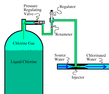
The most typical kind of chlorinator, a vacuum chlorinator with connection to chlorine cylinder, is shown in the below figure:

Vacuum Chlorinator with connection to Chlorine Cylinder
In a vacuum chlorinator, chlorine gas is pulled from the cylinder into the source water by a vacuum. The vacuum is created by water flowing through the injector and creating a negative head. This negative head forces open the pressure regulating valve on the cylinder and allows chlorine gas to flow out of the cylinder into the chlorinator.
Once the gas has entered the chlorinator, the chlorine feed rate is measured using an indicator known as a rotameter. Just beyond the rotameter, the chlorine gas flows past a regulating device (a V -notch plug or a valve) which is used to adjust the chlorine feed rate.
Then the chlorine gas is pulled into the injector, also known as an ejector. The injector consists of a pipe filled with flowing water. The flowing water pulls chlorine into the water, both chlorinating the source water and creating a vacuum in the chlorine line which pulls more chlorine gas out of the cylinder. This type of chlorinator is also known as a solution feeder since the chlorine gas is dissolved into a small amount of source water, which is then piped into the main line of water to be chlorinated.
Flow meter capacities shall accommodate the maximum capacity of chlorinator. Flow meter shall be manually adjustable and shall be capable of automatically adjusting the amount of chlorine fed through the chlorinator on the basis of an external signal. The chlorine shall be withdrawn from storage as a gas under pressure. The pressurized chlorine gas shall pass through pressure-reducing valves and vacuum regulators.
Chlorinators can be controlled manually (using the regulator) or with a controller. The most common type of controller is the flow proportional controller which automatically feeds chlorine based on the flow rate of the water.
Vacuum chlorinators are very safe since any break in the line will disrupt the vacu urn and close the pressure regulating valve. As a result, chlorine leaks are very uncommon.
Direct Feed Chlorinators
In few cases, direct feed chlorinators are used instead of vacuum chlorinators. In a direct feed chlorinator, the chlorine gas is under pressure and is pumped directly into the main flow of water. There, the chlorine is evenly dispersed into the water using a diffuser.
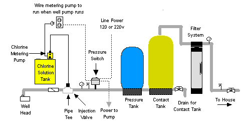
Since the chlorine is under pressure, a pressurized water supply is not needed for use with a direct feed chlorinator. However, the pressurized chlorine is prone to leakage, so safety issues limit direct feed chlorinators to small installations or for use as emergency equipment. The below figure shows the chlorine installation arrangement including pipe connection from cylinder to chlorinator and to discharge pipe.

Chlorinator Installation and Pipe Connections
Positioning of chlorine cylinder and containers
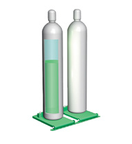
The chlorine is stored in the cylinder in liquefied form. While using for disinfection the liquid is passed through pressure reducing valve to convert again into gas. In chlorine cylinder or container some gas will be present on the top of the liquid. The chlorine cylinder is, therefore, kept upright as the outlet is on the top of the cylinder so that the gas available on the top of liquid surface can be withdrawn from the cylinder. Similarly the ton container should always be kept in horizontal position since the outlet is on the top end of the container as shown below.

Chlorine Cylinder
11 Responses to “CHLORINATORS”
Leave a Reply


 LIKE TO GET UPDATES
  TO GET EXPERT GUIDE
I like the layout of your blog and I’m going to do the same thing for mine.
How much percentage of nature water can drink directly in the world…
Below 5 % of water can drink directly without desalination…
http://www.thewatertreatments.com – оказывается ещё и полезный )
what are the cases in which there is need to use direct feed chlorinators instead of vacuum chlorinators?
Just follow this link
http://www.thewatertreatments.com/disinfection/chlorinators
if there is water supply on ground water which chlorinator is suitable
Inject 10 % Sodium hypochlorite solution on the drinking water line in the range of 0.2 – 0.4 ppm.This method is safety and less cost disinfection.
I have a problem with the rotometer floating up and down what would cause this to happen
ball in rotometer floats up and down and will not go above 70 lbs what is the cause of this
I want to know the dealers list with contact numbers working in Punjab Pakistan because I want to purchase Hypo Cholorinator
I want to purchase the Hypo Cholorinator for water supplies. Please send the name of dealer with contact number working in district Bahawalpur or nearest city in Punjab Pakistan.