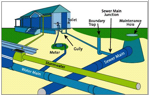

Design of Sewerage
The major shortcoming of the conventional design is the selection of pipe diameter and slope combination without fully analyzing the total cost of the entire sewer network. As it is done manually, numerous combination of pipe diameter with pipe slopes cannot be considered to arrive at an economical sewer system design. It is possible to overcome this problem by various optimization techniques and usage of computer to arrive at an optimum design of a sewer system.
An optimal design of sewer system is one which minimizes the total cost that includes the cost of pipes, cost of manholes, cost of laying and jointing of pipes, which should meet certain specification in relation to discharge, velocity etc., and any other alternative design for the same hydraulic conditions. The smallest feasible diameter and the minimum slope, so as to lay the pipe as close as possible to the surface are considered as optimal. Hence, a life cycle cost analysis of the pipes of different pipe materials and diameter is to be performed for selecting appropriate pipe material and an optimal design for a sewer network.
SEWER TRANSITION
Sewer transitions include change in size, slope, alignment, discharge, passing through measuring devices and sewer junctions. Manholes should be provided at all these transitions. Allowance for invert drops should be provided sufficiently for the head loss that occurs at these transitions with a minimum drop of 30 mm or the following whichever is higher in the manholes is recommended.
-
For the sewers of less than 400 mm diameter, half the difference in upstream and downstream diameters,
-
For the sewers from 400 mm to 900 mm two-thirds the difference in upstream and downstream diameters, and
-
For the sewers above 900 mm diameter, four-fifth the difference in upstream and downstream diameters.
MANHOLES AND THEIR SPACING
Manholes are of either masonry or concrete and should be provided at sewer transitions, change in direction and slope and also on straight reaches at convenient spacing. The spacing between the manholes is limited to 30 m for sewers up to 300 mm diameter and for larger diameters may go up to 100 m. Refer chapter 5 sewer appurtenances for more information about manholes.
HYDRAULIC PRINCIPLES
The flow in the sewer is assumed as steady state, and is always partially filled and never allowed to flow full. Open channel condition for closed conduit is assumed. The sewers should carry the peak flow for which it is designed and transport the suspended solids in such a manner that the deposit in the sewers is prevented.
In design practice, Manning’s formula for open channel flow is used and is given by:
V = —1x R213 x S112
Where,
V = Velocity of flow, m/s
n = Manning’s roughness coefficient
S = Slope of the sewer
R = Hydraulic mean radius, m
The normal values of n for S.W and R.C.0 pipes are 0.013 and 0.011 respectively.
The formula is used for the full flow condition. For partial flow conditions the velocity and discharge are derived from the appropriate hydraulic elements.
4 Responses to “Design of Sewerage”
Leave a Reply


 LIKE TO GET UPDATES
  TO GET EXPERT GUIDE
have you details about sewage treatment by/ext.activ.sludge/ MBR,/SBR,
hi….
Iam chemical engineer can I work in field of desgin of sewerage system
thanks..
hi….
I am chemical engineer can I work in field of design of sewerage system
thanks.
Of course you can work in designing the sewerage system and sewage treatment.
By Admin
hi..
i want to know about partially sewerage system..
thank you..
http://www.thewatertreatments.com/waste-water-treatment-filtration-purify-sepration-sewage/small-diameter-gravity-sewers
I suggested this blog is very useful for water treatment professionals do learn more..
Thank you!