
Trickling Water Filters
Trickling Filters in Waste Water Treatment

Trickling Filter
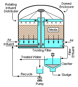
A Trickling water treatment filter (TF), an attached growth system, consists of a fixed bed of highly permeable media on whose surface a mixed population of microorganisms is developed as a slime layer. The fixed media in Trickling water treatments filter may be of rocks, plastic, metal, etc. In Trickling water filter there is no straining or filtering action involved. Passing of waste water after primary water treatment through the filter causes the development of a gelatinous coating of bacteria, protozoa and other organisms on the media. The waste water sprayed through a bed of coarse stones or plastic material packed in a circular tank. A rotating distributor (a rotating pipe with several holes across it) evenly distributes the waste water from the top of the bed. The waste water trickles down and collected by an under drain system. The microorganisms in the waste water attach themselves to the filter media in the bed and break down the organic matter and remove them from the wastewater.
The ideal filter medium is a material that has a high surface area per unit volume, has a high durability and high porosity so that clogging is minimized and good air circulation can occur. It’s cost should be low. The choice of filter media is generally governed by the material locally available.
Commonly used filter media are:
- crushed rock
- plastic packing
Crushed rock
Crushed rocks are typically used as filter media. Stones of less than 75 mm in size do not provide sufficient pore space and may result in clogging of the media. Large stones greater than 75 mm tend to avoid ponding situations but limit the surface area per unit volume available for the slime layer to grow. An upper size limit of the stones is about 150 mm. The material is, therefore, graded to a uniform size in the range of 75 to 150 mm. The depth of stone media is in the order of 1.5 to 2.0 m. Plastic Packing
The introduction of thermo formed PVC or synthetic material such as plastic rings and saddles as media is largely responsible for the success of the modern trickling filter. This advancement allows construction of modules of superior compressive strength and higher void-volumes necessary for stacking to heights not achievable with rock filters. Taller Trickling water treatment Filters, with heights up to 12 m with plastic media are known as bio-towers. Greater specific surface area makes higher organic loadings possible. Deeper bio-towers are easily ventilated through blowers because of the higher void volumes.
Rotary Distributor
The rotary distributor is used for spraying the waste water over the filter media of the Trickling Filters because of its reliability and ease of maintenance. The rotary distributor consists of a hollow vertical central column carrying two or more radial pipes or arms, each of which contains a number of nozzles or orifices for discharging the waste water onto the filter media. All of these nozzles point in the same direction at right angles to the arms. The force of the water causes the spray heads to rotate above the media, acting like a sprinkler and evenly distributing waste water across the media. The rotary reaction is furnished by a head of 450 to 600 mm. The speed of revolution will vary with the flow rate, but it should be in the range of one revolution in 10 minutes or less for a two-arm distributor.

clarifier
The liquid in fluent is piped through the bottom of the Trickling water treatment Filters to the distribution (rotating arm) heads, at the top of the trickling filter. The distribution head is generally not motorized, it is powered by jet action caused by the wastewater leaving the arm horizontally. With motor-driven rotary distributor center mechanisms, the performance of the trickling filters, is greatly improved and the problems associated with the old rotary distributors are eliminated. A clearance of 150 to 250 mm should be allowed between the bottom of the distributor arm and top of the media. This will permit the waste streams from the nozzles to spread out and cover the media uniformly.
Some cases, especially square or rectangular Trickling Filters, fixed flat-spray nozzles have been used.
Under drain System
The under drain system in Trickling Filters serves two purposes:
- To collect and convey the waste water passing through the filter and the sloughed solids
- from the filter to the SST, and
- To provide for ventilation of the filter to maintain aerobic conditions.
The under drains are open jointed SW pipes or specially designed vitrified clay blocks with slotted tops that admit the waste water and yet support the media. The blocks are laid directly on the filter floor, which is sloped toward the collection channel at 1 to 4 percent gradient. The effluent channels are sized to produce a minimum velocity of 0.6 m/ s at the average daily flow. Since the under drains also provide ventilation for the filter it is desirable that the total ventilation area of openings is at least 20 % of the total floor area. The under drains should be open to a circumferential channel for ventilation at the wall as well as to the central collection channel. The under drain and support system for plastic packing consists either a beam and column or a grating. Normal ventilation occurs through convection currents caused by a temperature differential between the waste water and the ambient air temperature. In deep filters or heavily loaded filters, there may be some advantage in force ventilation.
CYCLE OF OPERATION
A mixed culture of organisms grows on the media surfaces forming a dense bio film (slime layer) of viscous, jelly like mass. The bio film is a complex community of bacteria, fungi, protozoa and worms. It takes three to four weeks for the bio film to establish in the summer and up to two months in the winter. Waste water passes over the film in thin sheets. Dissolved organic compounds pass into the bio film due to concentration gradients and diffusion.
Suspended organic solids are trapped on the sticky surfaces and subsequently degraded by the bacteria. The bio film is made porous by the feeding activities of the grazing fauna, which are continuously burrowing through the film. Oxygen from air spaces in the solid media diffuses through the waste water film and into the bio film. Oxygen penetration will be for a depth of 0.2 mm in a bacterial film and between 3 and 4 mm in a fungal film. Metabolic by-products diffuse back to the waste water through the film and air spaces in the media. The film thickness may increase as much as 10 mm. Growth of bio film and increase in thickness makes it more difficult for oxygen to diffuse through the bio film. An anaerobic layer develops deep in the bio film causing weakened attachment to the media. Weakened attachment plus a thickened bio film layer eventually causes the waste water flow to shear off the bio film and wash it away. This shearing process is called sloughing. The bio film then reestablishes itself. Sloughing is occurred periodically and sloughed microbial growth is carried along with filter outflow. For this reason, trickling filters should be followed by secondary settling tanks (SST) to remove these sloughed solids by settling and to produce a relatively clear effluent. This sloughing cycle is continuously repeated throughout the operation of a trickling filter. For economy and to prevent clogging of the distribution nozzles, trickling filters should be preceded by primary settling tanks (PST) equipped with scum collecting devices.
Recirculation
Recirculation is a process by which the effluent from SST is returned to and reapplied along with inflow onto the filter. This recycling of the effluent increases the contact time of the waste with the microorganisms and also helps to “seed” the lower portion of the filter with active organisms. Recirculation of water through the fixed media filter is one method of controlling the microorganisms’ environment. It decreases the concentration of food, which can be either positive or negative depending on the F/ M ratio. Recirculation also increases the amount of oxygen in the water, which can help in the removal of B.O.D.
The degree of recirculation should be optimized so that the microorganisms work most efficiently. Recirculation also helps to minimize problems with responding and restriction of ventilation. Recirculation can be continuous or intermittent at constant or variable rate. Recirculating effluent to the trickling filter dilutes the in fluent waste water entering the trickling filter. Since the BOD removal process is first order (i.e., the rate of removal of BOD is affected by the initial concentration of BOD), recirculation helps distribute the loading evenly through the depth of the filter. It also helps to manage the diurnal variation in loading while maintaining a minimum wetting-rate throughout the day. In general, higher recirculation ratios produce better effluent quality.
The “Recirculation rate” is the percent of the average in fluent waste water flow which is recirculated through the trickling filter. The recirculation is generally expressed as a decimal. Typical recirculation rates range from 0.2 to 2.0.
Secondary Settling Tank
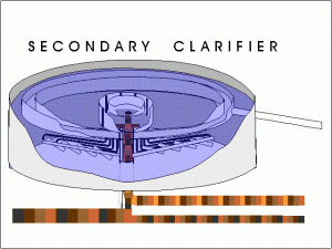
After this biological activity in trickling filter, a secondary settling tank is necessary to remove accumulated cells and any remaining solids, usually occurring in a circular tank with a conical bottom. The function of the SST is to produce a clarified effluent. Surface overflow rates of SSTs for TFs are similar in line with the design of SSTs used for activated sludge process.
DESIGN PARAMETERS
Hydraulic Loading
The hydraulic loading is one of the factors which will influence the performance of the filters. It is defined as the amount of waste water applied per day over the surface area of the media. It is expressed in Liters/ day/ square meter.
The hydraulic loading rate determines the length of time the organic constituents are in contact with the microorganisms and, hence, the extent of bio degradation that occurs. In trickling filters, the hydraulic loading rate also determines the shear velocities of the microbial layer. Excessively high hydraulic loading rates may wash away the microbial layer faster than it can grow back. However, the hydraulic loading rate must be high enough to keep the microbes moist and to remove dead or dying microbes hat have lost their ability to cling to the filter media. The hydraulic loading rate is controlled, by adjusting the waste water feed rate. Monitoring of the waste water feed rates is necessary to ensure that the hydraulic loading provides sufficient time to achieve an effective bio degradation of organic constituents in the waste water.
Organic Loading
The organic loading is the amount of B.O.D. applied to the filter per day per unit volume of filter media. So the units of organic loading are typically kg B.O.D./ day/ 1000 m3 of media. The organic loading also influences the performance of the filter. The organic loading can be calculated using the formula below.
Organic loading rate (lcgBOD I day 11000 )=
Total BOD Load (kg__ I d) x1000
Filter volume (m3 )
This formula does not include recirculation, so the flow used in the calculation of BOD load is the influent flow rather than the total flow.
Recirculation Factor
Recycle of treated wastewater is an effective method of keeping all areas and depths of the trickling filter biologically active when the influent flow is too low for proper wetting. Recirculation through PSTs requires extra capacity in these tanks, because the flow passing through them is increased. The volume of filter will not be affected by recirculation. The ratio of the volume of sewage recirculated (R) to the volume of raw sewage (I) is called recirculation ratio. Recirculation factor (F) is given by
1 + —
F= ______________
[1+ 0.1(R / /)]2
When there is no recirculation R/I is zero and F is unity
17 Responses to “Trickling Water Filters”
Leave a Reply


 LIKE TO GET UPDATES
  TO GET EXPERT GUIDE
I recently came accross your website and have been reading along. I thought I would leave my very first comment. Nice blog. I will keep visiting this blog very often.
It is nice to definitely dig up a blog where the blogger is well-informed. Thanks for creating your web site.
i recently came acroos your site and reading this.its seem very professional data.please became more data about wasteater engineering.thanks
Thanks for the information!
I recently came acroos your site and reading this.its seem very professional data.please became more data about wastewater engineering.espesialy about the method of determination and separation of old microorganisn and young microorganism on activated sludge processes?
thanks
Welcome. We will give more updates in wastewater engineering. Thanks lot for your kind support..
THANKS FOR YOUR GOOD INFORMATION AND PICTURES OF DIFFERENT METHOD OF WATER AND WASTE WATER TREATMENT.
very good information for students thank you.
I was surfing on the net and searching about different method in waste water treatment suddenly I saw your website oh it’s wonderful thank you thank you very much for your information
Thank you very much.It helped me lot for my
semester exams.
http://www.thewatertreatments.com/waste-water-treatment-filtration-purify-sepration-sewage/trickling-filters-filtration-sewage-treatment
This method is not effective in reducing TDS or removing soluble metals such as barium or radium, correct?
Too good about water treatment process and designs.
i really appreciate the info that u have placed over the net it is understandable thankx
Great post of content.Waiting for other cooling tower water treatment.
good
it is very nice blog……….having full of knowledge.
thanks to administrator..
Very nice instrument. I like it.